Buck Converter Size vs Frequency
Buck converters work with two energy storage devices, the inductor and capacitor. In such a switching power supply, the inductor is responsible for storing and transferring energy between input and output. The purpose of the capacitor is to smooth the output voltage by filtering the ripple current generated by the inductor. The desired value of both to maintain specific current and voltage ripple requirements is bound by the converter's switching frequency. In general, as switching frequency increases, the value of inductance and capacitance required to achieve certain design constraints decreases. This can lead to a more compact size, as physically smaller inductors and capacitors can be chosen.
Buck Converter: Refresher
A buck converter is a DC-DC converter that steps down the applied input voltage. The simplest implementation consists of a few key elements: a single switch (usually a MOSFET), an inductor, a capacitor, and a diode.
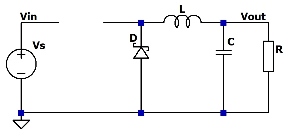
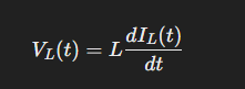
To understand how a buck converter works, the most crucial equation to remember is the voltage across an inductor:
When the switch is on, the inductor stores energy. When the switch is off, it releases this energy. Inductors resist change in current. So when the current path through the switch is suddenly interrupted (meaning a rapidly negative di/dt), a high voltage of opposite polarity is generated across the inductor, forward-biasing the diode. The diode provides an alternative path for current to flow (called the "freewheeling" path). This freewheeling phase gradually reduces the inductor's current in the half-cycle, since the inductor's voltage becomes constantly negative. At this point, the voltage across the inductor is nearly -Vout: the conducting diode is clamping the voltage at the left node to one diode drop below ground, and the right node is connected to the output capacitor at Vout. Thus, the voltage across the inductor is approximately -Vout.
The duty cycle (percentage of time the switch is closed during one cycle) affects the output voltage. During the time the switch is on, the inductor is connected to the input voltage, which pushes the output voltage upward. When the switch is off, the energy stored in the inductor is released through the diode, pulling the voltage back down.
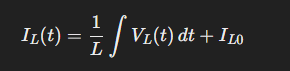
Voltage across the inductor must be 0 on average across a cycle. This ensures its current (and thus energy stored) is constant on average. More on that in the next section. The balance between the positive voltage of the on phase and the negative voltage of the off phase determines the relationship between Vin and Vout, with the duty cycle setting the proportion. An average voltage of 0 over each cycle means that the output voltage is proportional to the amount of time that the switch is on, since that is when the output voltage is being pushed up. Otherwise, it is just being pulled down toward 0 (during the off period). This is why a duty cycle of 100% corresponds to an output voltage equal to input voltage under ideal conditions.
The Inductor: Ripple Current
The inductor stores energy during one part of the switching cycle and releases it during the other. This results in a triangular-waveform ripple current, since the current through the inductor is constantly increasing or decreasing linearly within a cycle. As we examined in the previous section, during the on time, a constant positive voltage (Vin - Vout) is applied to the inductor. During the off time, a nearly constant negative voltage (-Vout) causes the current to decrease linearly. The decrease exactly cancels the increase because this all occurs during one cycle, split between the on and off time according to the duty cycle. Thus, the ripple current waveform is triangular. Looking at Equation 2, we can see that a constant voltage across the inductor means a linear increase in current.
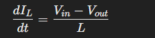
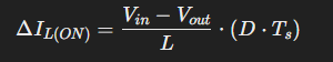
When the switch is on, the voltage across the inductor is simply Vin - Vout. Substituting this for Vl in Equation 1 and solving for di/dt:
The total on time is given by D * T, where T = 1/f (the switching period). Putting it all together, the total change in current for the on half-cycle can therefore be written as:
Since the ripple is symmetric (triangular waveform), the off time results in the same magnitude of current change. In other words, the current increase during the on period is exactly canceled out by the decrease during the off period. Therefore, the total peak-to-peak ripple current is the same. It can be simplified as:
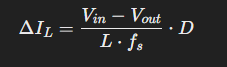
Substituting 1/f for T in the final equation gives us some valuable insight: as switching frequency increases, with a fixed duty cycle, ripple current decreases. So, with a higher switching frequency, the required inductance to achieve the same ripple decreases. This is why high-frequency converters can use smaller inductors, leading to a more compact design.
The Capacitor: Smoothing
The purpose of the capacitor is to smooth the voltage fluctuation caused by the ripple current. Even though the ripple current is 0 on average across a cycle, the ideal output of the buck converter should be a flat DC voltage. Output capacitors provide this smoothing by filtering the ripple current.
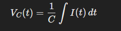
So, from Equation 6, we know that we are looking to find the area under the relevant current waveform in order to determine the change in charge on the capacitor (the integral represents the change in charge). This is not so straightforward because we are interested in the current through the capacitor, not just the ripple current.
The output capacitor must either absorb or supply the difference between the inductor current and the load current at any given time. If the inductor current is greater than the load current, then the capacitor charges. If the inductor current is less than the load current, then the capacitor discharges. In other words, the capacitor's voltage ripple results from integrating the difference between the inductor current and its average (which is the current that the capacitor actually "sees"). It is important to note that the inductor's average current is the load current (inductor current is a steady DC component plus the AC ripple). The maximum deviation from the average inductor current is ±ΔIL/2, centered on the average.
The net effect, across a switching period, is that the maximum or minimum capacitor voltage is reached only after accumulating charge over the time when current is unidirectionally above or below the average. This is all a really complex way of saying that the capacitor's voltage ripple is determined by the net area under the deviation of the triangular ripple from the average, which is always ΔIL/2 at the extremes. Since the triangle is symmetric in amplitude, this integration period corresponds to T/2 regardless of duty cycle.
For a triangle with a base of T/2 and a height of ΔIL/2, the area is:
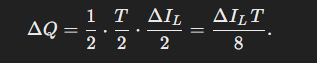
Substituting that area for the integral in Equation 6:
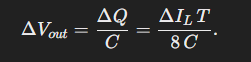
And since switching period T = 1/f, the final equation is:
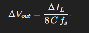
Just like with the inductor, this final equation leads us to the conclusion that increasing switching frequency decreases voltage ripple. This means that with a higher switching frequency, the required capacitance to achieve the same ripple decreases. So, again, higher-frequency designs can enjoy the benefits of using smaller parts.
Conclusion
Yes, there are downsides to higher switching frequencies. These downsides include increased switching loss, higher EMI, and design complexity. However, higher switching frequency designs can use smaller components and typically have better transient response, as the regulator can adapt quicker to changes in current demand. This article was just an explainer, from the ground up, on the impact of switching frequency on component size in buck converters. I wanted to prove the correlation with math from the very basics.